Room g02a robot control guide
Room g02a robot control guide
S. Wilcock 2023
- Room g02a robot control guide
- Installing Anaconda
- Installing COMPAS
- Starting the Ubuntu control PC and simulating with ROS
- Controlling the robot from Grasshopper
- Turning on the robot and preparing for real control
Gripper control and settings
First up we need to install Anaconda on your PC.
Installing Anaconda
University PC
If you’re running a university computer, Anaconda is included in the AppsAnywhere system. Visit https://appsanywhere.leeds.ac.uk/ , accept any installation requirements, validate etc. etc. If you need help with this step see the knowledge base https://it.leeds.ac.uk/it?id=kb_article&sysparm_article=KB0014827
With AppsAnywhere setup, it should then be a case of simply searching for Anaconda:

Personal PC
On a personal device follow the instructions here https://docs.anaconda.com/anaconda/install/index.html
Installing COMPAS
The initial setup is the same for both University and personal computers.
Anaconda allows us to create “virtual environments” that contain sets of Python packages. This is beneficial as it allows isolation of packages with different, clashing installation requirements, whilst acting as a sandbox of sorts.
First we’re going to create a new Conda virtual environment. In the start menu, search for “Anaconda” and run the Anaconda Prompt

Then, we will create the environment with the COMPAS and COMPAS_FAB packages installed:
conda create -n kuka_control -c conda-forge compas compas_fab
conda activate kuka_control
Then verify the installation:
python -m compas
> Yay! COMPAS is installed correctly!
At this point, you have created a new Python environment with the required software installed (keep the prompt open!). Now we need to tell Rhino/Grasshopper to add COMPAS as a plugin (this process depends on your computer type).
University PC
This is a bit of a pain on a Uni PC as we don’t have admin rights to install stuff properly. In Windows Explorer, visit
%USERPROFILE%\Anaconda3\envs\kuka_control\Lib\site-packages
Find all folders with “compas” at the beginning (but not dist-info as a suffix), AND THE ROSLIBPY FOLDER, select them and copy them.


We need to paste these into the Rhino scripts folder, found at
%APPDATA%\McNeel\Rhinoceros\{VERSION_NUMBER}\scripts
where {VERSION_NUMBER} should be replaced with your Rhino version, e.g.
%APPDATA%\McNeel\Rhinoceros\6.0\scripts
You will also need to copy the compas_bootstrapper.py file into this folder: compas_bootstrapper.py
(Fingers crossed this works…)
Personal PC
This is simpler on a personal computer as we have admin access. In the Anaconda Prompt you should be able to simply run:
python -m compas_rhino.install
or if you’re running Rhino 6
python -m compas_rhino.install -v 6.0
This may ask you to provide admin permission to run, don’t worry! It is just to create a so-called “symbolic link” to the Python installation files.
Verify installation to Rhino/Grasshopper
Within Grasshopper, create a new ghPython component and double click on it. Insert the following script and press test to verify that you receive a printed value for the version
import compas
print(compas.__version__)

import compas_fab
print(compas_fab.__version__)

Starting the Ubuntu control PC and simulating with ROS
The control PC is setup to be almost plug and play. First turn on the PC. If you are required to enter login credentials, use Username: ros Password: ros
Connect your personal computer to the free end of the blue ethernet cable, and then on the windows PC open a command prompt (Start > Command Prompt). Verify the connection to the Ubuntu box’s DHCP server using:
ping 172.31.1.150
all being well, you should receive something like
Ping statistics for 172.31.1.150:
    Packets: Sent = 4, Received = 4, Lost = 0 (0% loss),
Approximate round trip times in milli-seconds:
    Minimum = 0ms, Maximum = 0ms, Average = 0ms
(if not, ensure that your ethernet adapter settings are set to Automatic (DHCP)).
On the desktop of the Ubuntu PC are icons allowing simulation or real control modes to be run. First, double click the icon to Simulate the robot. The terminal (bash) window which pops up should provide debugging information for the (simulated) robot

The RVIZ window allows graphical interaction with the robot

^ Here the goal position of the robot end-effector can be seen as being altered.
On the left we have the Motion planning and displays tabs. In the MotionPlanning tab, we can plan and execute paths for the robot, and select preprogrammed manipulater positions

Additionally within the MotionPlanning tab is a scene object section, which allows us to view any collision objects that we have in the planning scene

Additionally there is the display tab allowing us to alter the displayed graphics. In here the most important section for us is the MotionPlanning tab. When in simulation mode ONLY, we can change the planning group to move the gripper instead of the arm

There are 2 versions of each script on the desktop: one normal, and one labelled debug. The debug mode will display robot trajectories on screen as green lines, and will not execute until you press “Next” (at the bottom). In this way we can observe trajectories first and ensure that there will be no collisions.
When learning to use the robot, make use of this simulation and debug mode before handling the real device!
Controlling the robot from Grasshopper
With your PC connected to the Ubuntu box and with a robot program running (simulated OR real), open the following demo file: iiwa_gh_demo.gh
On opening, the GH definition is split into three colour regions. Blue is setup/input, red is for reach data, and green is for interacting with the ROS ubuntu PC.
First we need to connect to the PC. Click the connect button. If you have an old connection it can be useful to first press Disconnect and Flush first 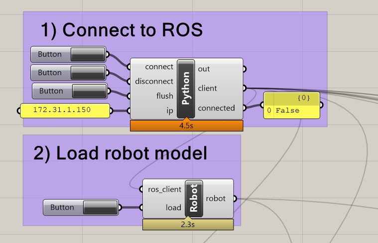
Then underneath that we have a button to load the robot model into Grasshopper. Note that the first time this is loaded will take around 30 seconds, but should be quicker subsequently as it is set to create a cache folder locally.
Once the robot model is loaded, you should see an representation of the arm in Rhino. Note that pressing the trigger button in the load joint_states group should update the model with the current joint angles - this can be set to continuously fire with a timer (included) 
The end effector pose can be acquired in a similar manner. Note here the terminology; positions are locations in XYZ, poses additionally provide rotational information. To achieve this information, the pose is returned as a plane 
The reachability data for the arm can also be accessed 
Accessing ROS services and topics
ROS works on a framework of transmitting data via topics and service calls (have a look at http://wiki.ros.org/Topics for more on how it works). In order to access them from Grasshopper (via the COMPAS FAB library) some demonstration nodes have been created.
First is this node which lists all of the possible services and topics currently running on ROS

Following that are two nodes for controlling the robot by specifying its end-effector position/pose:

Note that for the position control, the robot will plan (via Moveit) for any random orientation about the desired point. Don’t put it too close to the ground(!)
There is also a Cartesian movement node. Note that Cartesian movements are defined by straight lines between two poses. They don’t necessarily work amazingly currently, due to the implementation based on MoveIt’s interpolation of poses. This would be a good area to upgrade (using Descartes or similar).
The gripper control service will alter the width of the parallel jaw gripper, in mm

It is useful to be able to add collision objects into the planning scene. Moveit will plan to avoid hitting objects. The node here allows us to insert mesh objects (keep resolution low for faster planning and exporting). This is a useful method for adding walls, tables etc. Note that Moveit can “grip” collision objects to move them, by converting them into AttachedCollisionObjects, although this is beyond the scope of this demo.

Finally the joints can be controlled directly. Note that this bypasses planning, and as such also collision avoidance! The /iiwa/gh_trajectory service that it calls will allow multiple points to be sent with timings as a trajectory of motions. This could be useful if you plan on using alternative planning software, e.g. HAL, kukaPRC…

Turning on the robot and preparing for real control
First switch on the robot by the green button on the back

Once started, the Kuka software annoyingly has a minor issue with the screen resolution which can be fixed easily. Turn the switch at the top to the settings/gear icon.
Press the blue bar to unload the control connection and then press again to reload it (this seems to fix the screen issue! It’s an RDP thing ![]() )
)
This screen normally allows the selection of control mode: T1 should be used for manual control of the axes/end-effector (jogging), whilst AUT should be used for running programs. Select AUT and move the physical switch back to the vertical position.
To get ready for control, first perform and safety checks on the area, then, ensuring the BRB (BIG RED BUTTON) is not pressed in, select ROSSmartServo from the “Applications” drop down menu

The program can then be started using the “Play” button on the left. The program awaits communication from the control PC.

Then, the “Start robot control” script should be run from the Ubuntu desktop. Once RVIZ loads, you should see the robot model on screen move to match the real robot’s pose.
With this running, the robot control should now be live! It is controllable in the same way as the simulation. Turn down the speed on the robot smartPAD to around 20% for safety (I’ve programmed in some hard speed limits on the KukaSunrise so if you don’t do this the robot will likely keep stopping).

Sending commands from Grasshopper or RVIZ should now directly control the robot! Remember to keep close to the BRB (big red button aka emergency stop) and if you have to shut down the software/restart, it should be done in this order:
- Stop the smartPAD program
- In the smartPAD applications menu, press the little reset button at the top
- Now you can close the terminal window on Ubuntu
If the terminal window is closed and the ros software killed, the smartPAD application cannot shutdown properly and the robot will probably need restarting. You can get around this by running roscore on Ubuntu while you stop.
Additionally on the smartPAD you should, with the smartServo software running, see some user menus on the left

The gripper menu allows opening and closing of the gripper for testing purposes. The hand guiding mode should be USED WITH EXTREME CAUTION! If you don’t know what you’re doing with this mode steer clear. Safety requirements for hand guiding should include:
- A buddy in control of the smartPAD handling the big red button
- Eyewear
- Quick reflexes like a cat
- Proper calibration of load data within the smartPAD robot menu
- Don’t be near a singularity
- Holding onto the gripper with two hands and making slow, controlled movements.
Missing any of these safety requirments can end up with black eyes, broken materials, and a robot that needs remastering. Again, if you don’t know what you’re doing here JUST. DON’T.
Gripper control and settings
The gripper is controllable via services as demonstrated in the Grasshopper demo file. Alternatively, while the robot is switched on but the ROS software is NOT running, the gripper can be accessed from either the host ubuntu PC or the control PC via this link http://172.31.1.140. See the Schunk WSG050-110 manual for info. The gripper requires “homing” to a known position to calibrate it before moving. This is automatic with the control software, however if you wish to test it through the web interface see the “Motion” tab.